1:20 scale model wind tunnel build - help!
Printed From: BHPC Forum
Category: Public: Open to anyone
Forum Name: Building
Forum Description: Anything to do with building HPVs
URL: https://forum.bhpc.org.uk/forum_posts.asp?TID=5134
Printed Date: 26 March 2026 at 11:30pm
Software Version: Web Wiz Forums 12.07 - https://www.webwizforums.com
Topic: 1:20 scale model wind tunnel build - help!
Posted By: russellbridge
Subject: 1:20 scale model wind tunnel build - help!
Date Posted: 02 May 2015 at 11:33am
|
Intention: - To build a 1:20 scale wind tunnel - To print models of HPV’s using a Makerbot Replicator 3D printer (I’ve just bought a s/hand one for work-ish  ) )- To be able to test the relative CdA of various models using a repeatable, accurate test Method - The wind tunnel is a straight-through wind tunnel using a ‘contraction’ section, a ‘test’ section, and a ‘diffuser’ section, with the fan at the rear to pull the air through - The whole wind tunnel will be made of 4mm Perspex, as I got a large sheet cheap at B&Q (damaged on one corner) - The design of the wind tunnel is as shown on the drawing below:  - The drag will be tested by mounting the model on a re-usable Lego ‘dolly’ and this will push against a digital weighing scale. I realise that I could use strain gauges instead but I don't want to get into electronics... Issue - What wind speed to use in the tunnel? - My understanding is that there are two equations to use – a ‘drag force equation’ and a ‘Reynolds number equation’ - Drag Force equation: Fd = ½ ρ v² Cd A - Reynolds number equation: Re = (ρ v L)/μ My simple understanding (maybe incorrect?) is that Cd is related to Re, so in the Re equation, if L divides by 20, then v needs to increase by 20. So, if the real world speed is 10m/s, then a 1:20 scale wind tunnel needs to be v x 20 ie 200m/s (or about 450mph). Is this correct? Achieve-ability Even at this small 1:20 scale the wind tunnel is 1.2m long, using a 380mm domestic box fan. I’ve yet to get hold of the fan, but I’d guess that the speed of air will be about 10m/s. Using a 4:1 ratio for ‘test area’ to ‘fan area’ means that I can only achieve about 40m/s, or 90mph. I don’t know what effect that this will have on the validity of the tests. Will this make the results invalid? If it does, is there any way to correct them, other than: - Increasing fan speed - Using water instead of air (not practical) - Increasing the scale of the whole thing |
Replies:
Posted By: jdp298
Date Posted: 03 May 2015 at 10:28pm
|
You could increase velocity to make up for the lack of length, but that'd be placing you in unrepresentative velocities. It would be better to accommodate Re through temperature and or pressure (e.g. ¼-scale would need x4 pressure, or lower temps to increase viscosity). However neither are going to be possible in your setup. Cd is related to many things, mostly down to bluff-ness of the bodies, their length, lift characteristics and separation i.e. where the transition from laminar to turbulent occurs. There are also some engineering bodges which sometimes work in your favour. I mean that through a range of Re, Cd may not alter by a large amount, which reduces your need to scale pressure and viscosity as much. These are fairly well known for aircraft components, but not so for bikes. So you won't get absolute data. However, you can represent relative effects, and measure one design against another. Similarly you can seek reductions and improvements in designs , even if you won't have a truly scalable number to set against it. ------------- I'll have a beer and money sandwich; hold the bread |
Posted By: GeoffBird
Date Posted: 04 May 2015 at 3:08pm
|
Hi Russell - yes your understanding about wind speed required for the same Reynolds Number is correct. As Jon says, having a different Re doesn't invalidate e results - we used to test 40% or 50% models of Le Mans cars at about 30 m/s, which is equivalent to about 30 mph full scale. With experience, the tunnel results could be correlated to reality, but it was known, for instance that diffuser ramp angles could be greater on the real car as separation did not occur as it did on the model. I would think that 'purer' streamlined shapes would be less affected by such phenomena though. You will get better results the less 'blockage' there is from the model, so the percentage of the tunnel test-section cross sectional area filled by the model frontal area. IIRC, they usually tried to keep this below 10% but I could have remebered this wrong. High blockage causes a venturi effect that speeds the air up over the model. Again, this is probably less critical for streamlined shapes - an Formula One car rear wing sends a rooster tail of air about 2 metres upward, so require tall test sections. Wind tunnels, like CFD are best for comparisons unless you have lots of data to get a correlation between reality and model testing ------------- Right Time - Right Place - Wrong Speed |
Posted By: Yanto
Date Posted: 06 May 2015 at 12:34pm
| Russ, I can't help with the theories. However, i have an observation, using the digital weighing scales at 90 deg to their designed orientation may introduce all kinds of variables that you cannot quantify, these may also vary with changes in applied force. |
Posted By: russellbridge
Date Posted: 16 May 2015 at 8:32pm
|
Well, the wind tunnel is all built now and the first run is done, with a small cube in the tunnel to test it, but the fan isn't strong enough. The 'desk fan' Draper box fan is only producing 9mph wind speed in the smaller test section, giving tiny readings of about 2g of sideways force. (the digital scales on their side seem to be functioning OK so far FYI Ian, and are self zero-ing upon turn on - can't grumble for £5 off ebay!) Time to find a new fan - I think I can squeeze a decent 350mm axial extractor fan in there which should give 2600m³/hr airflow. Will report back with some photos / videos when it's working a bit better. Russ ps Geoff I didn't get that .stl file - let me know if you tried to send it.
|
Posted By: Yanto
Date Posted: 16 May 2015 at 9:10pm
look out pedant attack: when i were a lad grams weren't a force, can i have my force in Newtons please? something like 0.0196133N 
|
Posted By: GeoffBird
Date Posted: 17 May 2015 at 4:17pm
|
Sorry Russell - slipped my mind. You should have it now. ------------- Right Time - Right Place - Wrong Speed |
Posted By: GeoffBird
Date Posted: 17 May 2015 at 4:27pm
You follow in illustrious footsteps - here is the wind tunnel built by the Wright brothers in 1901: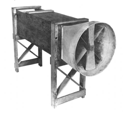 Exciting project! ------------- Right Time - Right Place - Wrong Speed |
Posted By: AlanGoodman
Date Posted: 17 May 2015 at 5:10pm
|
Pah! That'll never get off the ground... ------------- |
Posted By: GeoffBird
Date Posted: 25 May 2015 at 2:01pm
Russell has very kindly made me a !:20 scale rapid prototype model of my trike: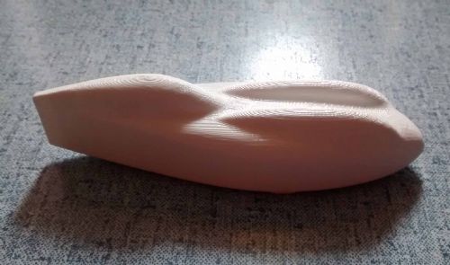 ------------- Right Time - Right Place - Wrong Speed |
Posted By: russellbridge
Date Posted: 29 June 2015 at 10:20pm
|
OK well some progress has been made. The fan has been replaced with a 350mm, all metal, commercial extract fan, which is producing around 31mph in the test section. Some way off the required 400mph but it'll have to do! Photos here:  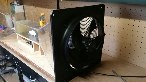 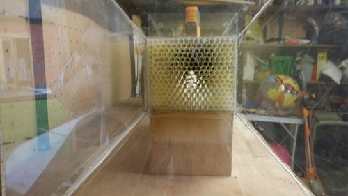 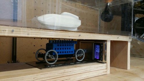 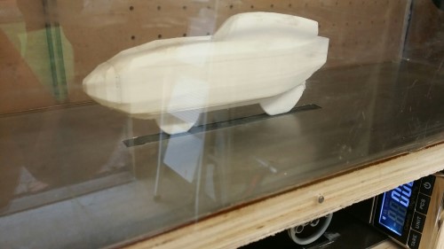 The test section of the wind tunnel seems to work really well - if you insert a piece of string or cotton through the flow straightener and into the test section it holds almost level and without turbulence until almost the end. I've also 3D modelled 6 existing fully-faired HPVs to give some kind of benchmark: - Slash's Beano - Jack and Derrick's Donkey - Davis? frame with blue sock - LeeW correx Challenge Fujin (above) - Correx boxed misc frame? - Geoff's HPV Heaven streamliner So far I've only 3D printed one as a test - LeeW's correx machine - printed at 1:18 scale. I ran it as a test tonight for the first time - unfortunately it's highlighting a measurement issue - the lego dolly is producing too much stiction so the results are too innacurate - three separate runs resulted in 2.xxg, 3.xxg and 4.xxg of horizontal force (or Newton equivalent to keep Mr Perry happy ) ie far too much error to produce consistent results.Youtube video here hopefully: So I'll have to investigate very low capacity load cells to solve the measurement issue (no idea where to start here quite frankly - any ideas anyone?) , and maybe up the print scale to 1:15 - I think the test section will take it OK.
|
Posted By: GeoffBird
Date Posted: 29 June 2015 at 10:47pm
|
Wow, that's brilliant Rus! Proper Job. Could the lack of repeatability (technical term  ) be down to something else? The old MIRA model tunnel (an open loop design like yours) used to give different results if someone opened the door to the room it was in! Is the anemometer (if you can say that word then you are still sober!) showing a constant airspeed? ) be down to something else? The old MIRA model tunnel (an open loop design like yours) used to give different results if someone opened the door to the room it was in! Is the anemometer (if you can say that word then you are still sober!) showing a constant airspeed?Load cells in wind tunnel balances are usually a flexible metal support with a piezoelectric wire glued to it. That's as far as my electrical knowledge goes I'm afraid. Should be fairly easy to make one and link it up to a meter. You could then calibrate it by mounting it vertically and applying weights. Someone with some knowledge of electrickery will tell you if I'm talking b#ll#@ks ------------- Right Time - Right Place - Wrong Speed |
Posted By: russellbridge
Date Posted: 30 June 2015 at 9:17am
|
Thanks Geoff - praise from Caesar! It is in a shed with a big door, but all the tests were done with the door closed so I don't think it's this. The wind speed is stable at between 30-31mph. I'll have to do some research on load cells or equivalent... These are the bikes I've used: 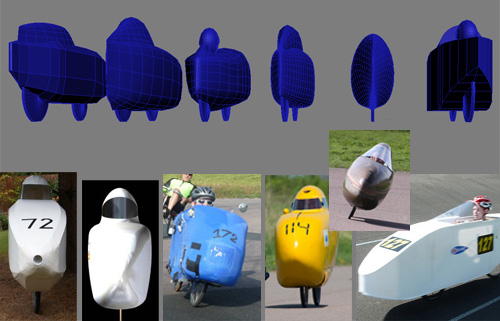 from left to right: - LeeW correx Challenge Fujin (above) Length: 2660mm Effective frontal area: 0.358m² - Geoff's HPV Heaven streamliner Length: 2540mm Effective frontal area: 0.443m² - Davis? frame with blue sock Length: 2360mm Effective frontal area: 0.395m² - Jack and Derrick's Donkey Length: 2300mm Effective frontal area: 0.340m² - Slash's Beano Length: 2230mm Effective frontal area: 0.309m² - Correx boxed misc frame? Length: 2590mm Effective frontal area: 0.419m² Please could anyone with access (esp. to Beano and Donkey) check the length measurements for me - I've scaled them from photos / wheel diameters - so there may be some errors above - looking at this fresh this morning, both Donkey and Beano look a bit too small in comparison to the others. I'll correct them if there are...
|
Posted By: SamR
Date Posted: 30 June 2015 at 5:42pm
|
This looks like it's coming on really well. The "Correx boxed misc frame" is one of the earlier Crusaders on a Davis D6 frame. That body no longer exists (split in half on the way to an event) but it had a length of 2340m and a frontal area of 0.383sq m not including the wheel.
|
Posted By: GeoffBird
Date Posted: 30 June 2015 at 6:33pm
This any help: I think the blue bike is the Kingcycle Wasp now owned by Andy TS - don't forget to model the gaffa tape  ------------- Right Time - Right Place - Wrong Speed |
Posted By: GeoffBird
Date Posted: 30 June 2015 at 6:35pm
|
I made the HPV-Heaven frontal area 0.4 m2 BTW. ------------- Right Time - Right Place - Wrong Speed |
Posted By: atlas_shrugged
Date Posted: 30 June 2015 at 9:15pm
|
Could you use an air bed rather than a trolley dolly to reduce stiction? It would be good to also model Ristretto Brian |